
A p-n junction may look like nothing more than two semiconductor regions joined together. Still, an invisible potential barrier quietly forms at their boundary and controls how charge carriers move.
How does this built-in potential form, why does it stop further diffusion, and how can we derive its exact value? Let’s uncover the physics behind the built-in potential, step by step.

Contents
Toggle🌟 Introduction
When a p-type and n-type semiconductor are joined, the concentration gradient between the n and p regions causes charge carriers to diffuse across the junction. As electrons and holes recombine near the junction, only positive immobile ions on the n-side and negative immobile ions on the p-side are left behind near the junction. This region is called the depletion region.
Due to these immobile ions, an internal electric field is created near the junction. This field produces a voltage across the junction called the potential barrier or built-in potential.
The potential barrier plays a very important role because it opposes further diffusion of majority carriers across the p–n junction and helps maintain equilibrium at the junction. It also determines the diode’s behavior when an external bias is applied.
By the end of this article, you will not only remember the formula
$$V_{b}=V_T\ ln\left(\frac{N_A N_D}{n_i^2}\right) $$
but also understand where it comes from, why the barrier forms, what it means physically, and how it controls the behavior of a p-n junction.
Potential Barrier (Built in Potential)
The potential barrier is defined as
The potential difference produced across the depletion region of a p–n junction diode due to the internal electric field created by immobile acceptor and donor ions is called the potential barrier.
Typical values of the potential barrier at room temperature are the following:
- Silicon ≈ 0.7 V
- Germanium ≈ 0.3 V
Derivation of Potential Barrier
The following figure shows the energy band diagram of a p-n junction diode, highlighting the potential barrier VB.
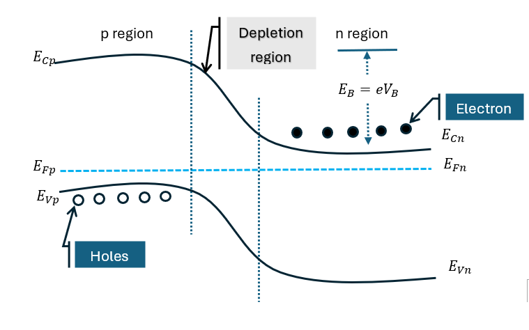
The barrier potential VB can be derived using the electron concentration in the n and p regions of the junction diode. The electron concentration in the conduction band of the n region is given by
$$n_n=N_cexp\left[ -\left( E_{cn}-E_{Fn} \right)/kT \right] ———(1)$$
Similarly, the electron concentration in the conduction band of the p region is given by
$$n_p=N_cexp\left[ -\left( E_{cp}-E_{Fp} \right)/kT \right] ———-(2)$$
Since the bottom of the conduction band in the p region is at Ecn + eVB. Therefore, equation (2) becomes,
$$n_p=N_cexp\left[ -\left( E_{cn}+eV_B-E_{Fp} \right)/kT \right] ———(3)$$
Dividing equation (1) by equation (3), we get
$$\frac{n_n}{n_p}=exp\left( \frac{eV_B}{kT} \right)$$ (Since at equilibrium EFn = EFp)
This equation is called Boltzmann’s equation.
Taking the logarithm on both sides of the above equation, we get
$$V_B= \frac{kT}{e}\log_e\left( \frac{n_n}{n_p} \right)$$
We can write the above equation as
$$V_B= \frac{kT}{e}\log_e\left( \frac{n_np_p}{n_pp_p} \right)———(4)$$
Since at room temperature all impurity atoms are ionized, therefore
$$n_n=N_D \quad and\quad p_p=N_A$$
where
ND = donor concentration
NA = acceptor concentration
And from the law of mass action, nppp = ni2
Hence, now equation (4) becomes
$$V_B= \frac{kT}{e}\log_e\left( \frac{N_DN_A}{n_i^2} \right)$$
This is the final expression for the built-in potential of a p–n junction diode.
Where:
VB = built-in potential (barrier potential)
k = Boltzmann constant
T = absolute temperature
e = electronic charge
NA = acceptor concentration
ND = donor concentration
ni = intrinsic carrier concentration
Physical Interpretation of barrier potential
For a higher doping concentration (NA or ND), there is a higher potential barrier, whereas a higher concentration of intrinsic carriers lowers the potential barrier. An increase in temperature modifies the barrier slightly.
Importance of barrier potential
The barrier potential is an essential part of a p-n junction because it controls the flow of charge carriers across the junction. It prevents further diffusion of the majority charge carriers from the p-region to the n-region and vice versa, thereby helping maintain thermal equilibrium.
The barrier also regulates the behavior of the diode when an external voltage is applied. Under forward bias, the potential barrier decreases, making it easier for current to flow.
Under reverse bias, the barrier increases and restricts current flow. Therefore, the potential barrier is essential to the proper operation of semiconductor devices.
Quick Answer Section/Interview Question
# What is built-in potential in a p-n junction?
The built-in potential is the voltage developed across the depletion region of a p-n junction when it reaches thermal equilibrium. It is produced by charge separation caused by diffusion of majority carriers across the junction. The resulting electric field opposes further majority-carrier diffusion and establishes equilibrium between drift and diffusion currents.
# What is the formula for built-in potential?
The built-in potential of an equilibrium p-n junction is given by
$$V_{bi}= \frac{kT}{q}\ ln\left(\frac{N_A N_D}{n_i^2}\right) $$
where (NA) and (ND) are acceptor and donor concentrations, ni) is the intrinsic carrier concentration, (T) is temperature, (k) is Boltzmann’s constant, and (q) is the electronic charge.
# What is the role of the depletion region in barrier potential formation?
The depletion region contains very few mobile majority carriers but contains fixed ionized dopants. These fixed charges establish the internal electric field responsible for the potential difference across the junction. Therefore, the depletion region directly forms the built-in potential.
# Can we measure the built-in potential with a multimeter?
No. Connecting a voltmeter creates additional metal-semiconductor contact potentials that exactly cancel the built-in potential, so an unbiased diode reads zero volts across its terminals despite the internal barrier existing.
🧮 Solved Numerical Problems
Problem 1: Basic Built-in Potential Calculation in Silicon
Question: A silicon pn junction is doped with NA = 2 × 1017 cm-3 on the p-side and ND = 1 × 1016 cm-3 on the n-side. Determine the built-in potential at room temperature (T = 300 K). Assume intrinsic carrier concentration ni = 1.5 × 1010 cm-3 and thermal voltage Vt = 0.0259 V.
Solution:
Given:
NA = 2 × 1017 cm-3
ND = 1 × 1016 cm-3
ni = 1.5 × 1010 cm-3
Vt = 0.0259 V
To find: Built-in potential (VB)
Calculation: Applying the built-in potential equation:
$$V_{B} = V_t \ln\left(\frac{N_A N_D}{n_i^2}\right) $$
Compute the numerator product:
$$N_A N_D = (2 \times 10^{17}) \times (1 \times 10^{16}) = 2.0 \times 10^{33}\text{ cm}^{-6}$$
Compute the denominator:
$$n_i^2 = (1.5 \times 10^{10})^2 = 2.25 \times 10^{20}\text{ cm}^{-6}$$
Evaluate the ratio:
$$\frac{N_A N_D}{n_i^2} = \frac{2.0 \times 10^{33}}{2.25 \times 10^{20}} = 8.889 \times 10^{12}$$
Take the natural logarithm:
$$\ln(8.889 \times 10^{12}) \approx 29.815$$
Multiply by the thermal voltage:
$$V_{B} = 0.0259\text{ V} \times 29.815 \approx 0.7722\text{ V}$$
Answer: The built-in potential of the silicon junction is 0.772 V.
Problem 2: Determining Donor Doping from Barrier Height
Question: An abrupt silicon junction at 300 K has an acceptor doping level NA = 1018 cm-3 and an experimentally verified built-in potential VB = 0.814 V. If ni = 1.5 × 1010 cm-3 and Vt = 0.0259 V, find the required donor concentration ND.
Solution:
Given:
VB = 0.814 V
NA = 1018 cm-3
ni = 1.5 × 1010 cm-3
Vt = 0.0259 V
To find: Donor concentration ND
Calculation: Invert the built-in potential formula algebraically:
$$\frac{V_{bi}}{V_t} = \ln\left(\frac{N_A N_D}{n_i^2}\right) $$
$$\exp\left(\frac{V_{bi}}{V_t}\right) = \frac{N_A N_D}{n_i^2}$$
$$N_D = \frac{n_i^2}{N_A} \exp\left(\frac{V_{bi}}{V_t}\right) $$
Compute the exponent:
$$\frac{0.814}{0.0259} \approx 31.4286$$
Evaluate the exponential term:
$$\exp(31.4286) \approx 4.4589 \times 10^{13}$$
Multiply by the minority carrier concentration ratio:
$$\frac{n_i^2}{N_A} = \frac{(1.5 \times 10^{10})^2}{10^{18}} = \frac{2.25 \times 10^{20}}{10^{18}} = 225\text{ cm}^{-3}$$
Calculate ND:
$$N_D = 225 \times (4.4589 \times 10^{13}) \approx 1.003 \times 10^{16}\text{ cm}^{-3}$$
Answer: The required donor concentration is ND = 1.0 × 1016 cm-3.
Problem 3: Temperature Shift on Built-in Potential
Question: A silicon pn junction has NA = 1016 cm-3 and ND = 1016 cm-3. At T1 = 300 K, its built-in potential is VB = 0.695 V. If the junction temperature rises to T2 = 350 K, causing ni to surge to 4.0 × 1011 cm-3, calculate the new built-in potential. (Note: at 350 K, Vt = kB T / q ≈ 0.03016 V).
Solution:
Given:
NA = 1016 cm-3
ND = 1016 cm-3
At T2 = 350 K: ni = 4.0 × 1011 cm-3, Vt = kB T / q ≈ 0.03016 V
To find: Built-in potential VB (350 K)
Calculation: Substitute the parameters at 350 K into the formula:
$$N_A N_D = 10^{16} \times 10^{16} = 1.0 \times 10^{32}\text{ cm}^{-6}$$
$$n_i^2 = (4.0 \times 10^{11})^2 = 1.6 \times 10^{23}\text{ cm}^{-6}$$
$$\frac{N_A N_D}{n_i^2} = \frac{1.0 \times 10^{32}}{1.6 \times 10^{23}} = 6.25 \times 10^8$$
Take the natural logarithm:
$$\ln(6.25 \times 10^8) \approx 20.253$$
Multiply by the new thermal voltage:
$$V_{B} = 0.03016\text{ V} \times 20.253 \approx 0.6108\text{ V}$$
Answer: At 350 K, the built-in potential drops to 0.611 V.
PYQs / Most Expected Examination Questions
Short Answer
- Define barrier potential.
- Write the expression for built-in potential.
Long Answer / Derivation
- Derive the expression for the barrier potential in a p–n junction diode.
- Explain the formation of the built-in potential using an energy band diagram.
Conclusion – barrier potential (built-in Potential)
The barrier potential is the internal voltage that forms in a p–n junction to control the movement of charge carriers. It plays a key role in diode operation by regulating current flow under different biasing conditions and forms the basis of semiconductor device behavior.
FAQs
1. What is barrier potential in a p–n junction?
The barrier potential is the voltage difference that develops across the junction of p-type and n-type semiconductors when they are joined. It acts as an internal electric field that prevents further movement of charge carriers across the junction.
2. How does barrier potential form in a p–n junction?
When the p-region and n-region come into contact, electrons and holes start diffusing across the junction due to concentration differences. This diffusion leaves behind charged ions, creating an electric field that opposes further diffusion. This opposition results in the formation of the barrier potential.
3. What is formula for barrier potential?
The built-in potential of a p–n junction is given by:
where k is Boltzmann's constant, T is temperature, q is the charge of an electron, NA and ND are doping concentrations, and ni is intrinsic carrier concentration.
4. What is the typical value of barrier potential in semiconductors?
For silicon, the barrier potential is usually around 0.6 to 0.7 V, while for germanium it is approximately 0.2 to 0.3 V at room temperature.
5. How does temperature affect the potential barrier?
As temperature increases, the potential barrier slightly decreases because more charge carriers are generated, which reduces the strength of the built-in electric field.
6. What is potential barrier and depletion region?
The depletion region is the area around the junction where mobile charge carriers are absent, while the potential barrier is the voltage developed across this region that opposes carrier movement.
7. Can the barrier potential be controlled?
Yes, it can be controlled by applying an external voltage (biasing). Forward bias reduces the barrier, whereas reverse bias increases it.
8. What is another name for barrier potential?
Another name for barrier potential is built-in potential.
It is also sometimes referred to as:
Junction potential
Contact potential
Among these, built-in potential is the most commonly used term in semiconductor physics.
9. Why is it called a barrier?
It is called a “barrier” because it acts like an obstacle that prevents charge carriers from freely crossing the p–n junction.